
Turnkey Solutions
Waste A–Z
Sectors
Project development
Engineering & Delivery
Operations & Lifecycle
Commercial & Investment Models
Warp Gasification
team@univastum.com
Knowledge Base
Chief Technology Officer
Peter Kalenuk
Industrial Waste-to-Steam
Integrated Waste-to-Steam facility for industrial client
Spain
Municipal Waste-to-Electricity
Modular Waste-to-Energy facility for municipal solid waste
Romania
investors@univastum.com
Chief Investment Officer
Eben Klynsmith
Our Approach
Work With Us
Insights & News
Press Kit
mt@univastum.com
Chief Marketing & Communications Officer
Matthew Tucker
About Univastum
Leadership & Governance
Careers
Sustainability
Alternative Fuel Gasification in the Cement Industry: Where It Actually Makes Sense
An engineering perspective on gasification, waste-to-energy integration and fossil-fuel substitution in cement production
Peter Kalenuk, PhD
Peter Kalenuk, PhD
The cement industry has been using alternative fuels for many years. RDF, SRF, prepared municipal and industrial waste, end-of-life tyres, biomass residues and other materials already replace coal and petroleum coke at hundreds of plants worldwide.
The key question, in my view, is therefore no longer whether waste can be used as an energy source, but in what form that energy should be introduced into the process of a particular cement plant.
Direct RDF feeding to a calciner or kiln remains the simplest and most economically rational solution in many cases. Gasification should not be positioned as an alternative to direct co-processing in every application, let alone as its universal replacement.
There is, however, a broad class of projects in which it makes engineering sense to add one thermochemical conversion stage between heterogeneous solid fuel and the cement process: to convert prepared waste into a controlled gaseous fuel.
This is where I see the principal role of gasification and waste-to-energy solutions in modern cement manufacturing.
The key question, in my view, is therefore no longer whether waste can be used as an energy source, but in what form that energy should be introduced into the process of a particular cement plant.
Direct RDF feeding to a calciner or kiln remains the simplest and most economically rational solution in many cases. Gasification should not be positioned as an alternative to direct co-processing in every application, let alone as its universal replacement.
There is, however, a broad class of projects in which it makes engineering sense to add one thermochemical conversion stage between heterogeneous solid fuel and the cement process: to convert prepared waste into a controlled gaseous fuel.
This is where I see the principal role of gasification and waste-to-energy solutions in modern cement manufacturing.
A Cement Plant Primarily Needs Thermal Energy
Clinker production is one of the most energy-intensive high-temperature industrial processes. Material in the sintering zone reaches approximately 1,450°C, while flame temperatures are substantially higher.
For 2022, the International Energy Agency reported average thermal energy intensity of approximately 3.6 GJ per tonne of clinker and, in its Net Zero pathway, indicated a reduction towards about 3.4 GJ/t by 2030.1
The economic value of syngas produced from waste is therefore normally greatest when its chemical energy directly replaces coal, petcoke or natural gas in the process, rather than when syngas is first converted into electricity.
In practical terms, the three principal integration points are: Hot Gas Generator (HGG) → calciner → kiln system.
These options differ significantly in integration complexity, process risk and potential energy impact.
For 2022, the International Energy Agency reported average thermal energy intensity of approximately 3.6 GJ per tonne of clinker and, in its Net Zero pathway, indicated a reduction towards about 3.4 GJ/t by 2030.1
The economic value of syngas produced from waste is therefore normally greatest when its chemical energy directly replaces coal, petcoke or natural gas in the process, rather than when syngas is first converted into electricity.
In practical terms, the three principal integration points are: Hot Gas Generator (HGG) → calciner → kiln system.
These options differ significantly in integration complexity, process risk and potential energy impact.
Alternative Fuels Are Already Part of the Industry Standard
The scale of this transition is important.
According to the Global Cement and Concrete Association (GCCA), the share of alternative fuels in its global industry dataset increased from 19.1% of thermal energy in 2020 to 22.7% in 2022. GCCA also reports cement kilns operating at very high, and in some cases near-complete, alternative-fuel substitution.2
Some international producers are already well above the global average. Holcim reported that alternative fuels supplied 39% of the thermal energy used for clinker production in 2025, while 14 of its European plants operated above 80% alternative fuels.3
This demonstrates two things at the same time.
First, a cement kiln is itself a highly effective co-processing system for suitable waste-derived fuels. There is little reason to gasify stable, high-quality RDF first if it can be fed safely, reliably and economically directly into the calciner.
Second, as the thermal substitution rate rises, feedstock constraints become increasingly important: particle size, moisture, ash chemistry, chlorine, sulphur, alkalis, LHV variability, transport and dosing behaviour.
This is where a distinct technological role for gasification begins to emerge.
According to the Global Cement and Concrete Association (GCCA), the share of alternative fuels in its global industry dataset increased from 19.1% of thermal energy in 2020 to 22.7% in 2022. GCCA also reports cement kilns operating at very high, and in some cases near-complete, alternative-fuel substitution.2
Some international producers are already well above the global average. Holcim reported that alternative fuels supplied 39% of the thermal energy used for clinker production in 2025, while 14 of its European plants operated above 80% alternative fuels.3
This demonstrates two things at the same time.
First, a cement kiln is itself a highly effective co-processing system for suitable waste-derived fuels. There is little reason to gasify stable, high-quality RDF first if it can be fed safely, reliably and economically directly into the calciner.
Second, as the thermal substitution rate rises, feedstock constraints become increasingly important: particle size, moisture, ash chemistry, chlorine, sulphur, alkalis, LHV variability, transport and dosing behaviour.
This is where a distinct technological role for gasification begins to emerge.
Why Convert RDF into Gas if It Can Be Used Directly?
I would describe the difference in the following way.
With direct co-processing, the cement process must adapt, to some extent, to the physical and chemical characteristics of the solid alternative fuel.
With gasification, we first transform the fuel and then introduce its energy into the cement process. These are fundamentally different approaches.
With direct co-processing, the cement process must adapt, to some extent, to the physical and chemical characteristics of the solid alternative fuel.
With gasification, we first transform the fuel and then introduce its energy into the cement process. These are fundamentally different approaches.
Gasification is therefore most attractive where direct RDF utilisation is constrained not by energy content itself, but by physical properties, ash chemistry, feeding stability or the requirements of a specific kiln line.
I also consider a hybrid configuration entirely rational:
I also consider a hybrid configuration entirely rational:
high-quality RDF → direct co-processing, while more difficult prepared combustible streams → gasification → syngas
A cement plant does not have to choose a single technological philosophy.
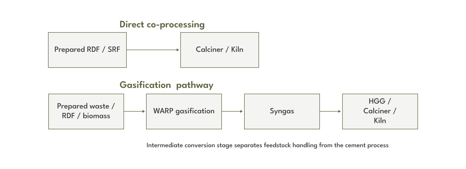
Figure 1. Direct co-processing and gasification as complementary alternative-fuel pathways.
Where to Start: Hot Gas Generator Integration
For a brownfield project, I would normally begin the gasification assessment not with the main kiln burner, but with the lowest-risk point of integration: the Hot Gas Generator (HGG).
HGG systems are already used in cement and related mineral industries to provide hot gas for drying raw materials, coal and other wet process materials.4
For gasification, the energy chain is straightforward:
HGG systems are already used in cement and related mineral industries to provide hot gas for drying raw materials, coal and other wet process materials.4
For gasification, the energy chain is straightforward:
RDF / SRF / waste / biomass → WARP gasification → syngas → HGG → hot drying gas.
The generated heat can be used for drying raw materials or raw meal, coal and petcoke, RDF/SRF and other alternative fuels, mineral additives, or other materials requiring an independent hot-gas source.
From the perspective of a first industrial deployment, HGG integration has several important advantages. Syngas is not introduced directly into the clinker-forming zone, so the risk of affecting clinker mineralogy or the core kiln operation is materially lower. The HGG can remain a separate thermal island, while the existing fuel system is retained as backup.
Most importantly, this configuration generates the operating data needed for the next stage of the project: real syngas quality, pressure stability, contaminant loading, burner behaviour, availability and the actual cost per GJ of useful thermal energy delivered.
For this reason, I see an HGG not only as a commercial application in its own right, but also as a logical first qualification stage for a gasification system at an operating cement plant.
From the perspective of a first industrial deployment, HGG integration has several important advantages. Syngas is not introduced directly into the clinker-forming zone, so the risk of affecting clinker mineralogy or the core kiln operation is materially lower. The HGG can remain a separate thermal island, while the existing fuel system is retained as backup.
Most importantly, this configuration generates the operating data needed for the next stage of the project: real syngas quality, pressure stability, contaminant loading, burner behaviour, availability and the actual cost per GJ of useful thermal energy delivered.
For this reason, I see an HGG not only as a commercial application in its own right, but also as a logical first qualification stage for a gasification system at an operating cement plant.
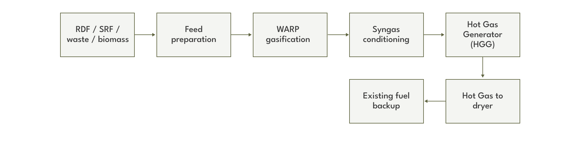
Figure 2. HGG integration keeps the first gasification step outside the clinker-forming process.
From HGG to the Calciner: A Phased Implementation Sequence
For an operating cement plant, I would recommend a staged implementation sequence rather than immediate integration with the most process-sensitive fuel point.
Stage 1 - Screening and Design Basis
The first step is to characterise the kiln line, existing fuel mix, HGG systems, consumption of coal, petcoke and natural gas, current thermal substitution rate, available waste streams, site space and energy costs. Representative feedstock analysis should cover at least LHV, moisture, ash, chlorine, sulphur, alkalis and metals.
At this stage, the question is not which gasifier to buy. The first question is: which fuel do we want to replace, at which process point, and how much useful thermal energy is required?
At this stage, the question is not which gasifier to buy. The first question is: which fuel do we want to replace, at which process point, and how much useful thermal energy is required?
Stage 2 - Material and Energy Balance
The project balance should then follow the full energy chain:
waste input → prepared fuel → gasification → syngas → useful thermal energy.
This establishes required feed rate, syngas flow, LHV, expected composition, sensible heat, auxiliary consumption, ash flow and gas-conditioning requirements.
This is the point at which it becomes possible to determine whether the project has a credible energy basis.
waste input → prepared fuel → gasification → syngas → useful thermal energy.
This establishes required feed rate, syngas flow, LHV, expected composition, sensible heat, auxiliary consumption, ash flow and gas-conditioning requirements.
This is the point at which it becomes possible to determine whether the project has a credible energy basis.
Stage 3 - HGG Integration
Where a continuous drying load exists, HGG integration is usually the preferred first connection point. It can validate real gasification performance without direct interference with clinker formation.
Stage 4 - Partial Substitution in the Calciner
Once syngas specification and operating stability have been demonstrated, the calciner is the next logical step. At this stage, gas volume, oxygen balance, residence time, temperature profile, induced-draft fan capacity and the effect on the overall kiln gas balance must be modelled.
For preliminary engineering, substitution scenarios of approximately 20-30% can be used as calculation cases, not as guaranteed performance levels. The achievable thermal substitution rate must be established for the actual kiln configuration.
For preliminary engineering, substitution scenarios of approximately 20-30% can be used as calculation cases, not as guaranteed performance levels. The achievable thermal substitution rate must be established for the actual kiln configuration.
Stage 5 - Selected Kiln Burner Applications
The main kiln burner can offer high value, but it is also more sensitive to flame shape, momentum, radiation and production stability. I would therefore move to selected kiln-burner applications only after sufficient operating data have been accumulated at lower-risk consumers.
Stage 6 - Integrated Energy Configuration
In the mature configuration, one gasification island can supply several syngas consumers: HGG, calciner, selected burners and, where economically justified, electricity generation or heat-recovery systems.

Figure 3. A staged path from feedstock qualification to integrated plant-wide syngas use.
This approach reduces technical risk. Instead of requiring the cement producer to expose the most critical process area to a new fuel system from day one, the level of integration increases as real operating evidence is accumulated.
What Is Different About Univastum WARP?
Gasification is not a single technology. Its performance depends strongly on reactor architecture, temperature regime, oxidant strategy, fuel movement, gas withdrawal point and downstream gas conditioning. The important question is therefore not simply whether gasification is used, but how the gasification platform is engineered for the intended industrial duty.
For cement applications, several features of WARP are particularly relevant.
For cement applications, several features of WARP are particularly relevant.
Modular architecture
For preliminary project design, a standard WARP module is based on approximately 5 t/h of prepared fuel. With RDF/SRF in a typical LHV range of roughly 14-22 MJ/kg and an indicative feedstock-to-syngas energy conversion factor around 0.75, one module corresponds to approximately 15-23 MWth of syngas chemical energy.
Multiple modules can supply a common clean-syngas header at a large cement plant. This allows gasification capacity to be matched to actual site thermal demand and provides a modular rather than single-reactor architecture. Individual trains can be isolated for maintenance while the remaining modules continue operating, subject to the plant configuration.
Multiple modules can supply a common clean-syngas header at a large cement plant. This allows gasification capacity to be matched to actual site thermal demand and provides a modular rather than single-reactor architecture. Individual trains can be isolated for maintenance while the remaining modules continue operating, subject to the plant configuration.
High-temperature syngas withdrawal
In the WARP design, hot raw syngas is withdrawn from the upper high-temperature section of the reactor, typically at approximately 900-1,000°C. The purpose of this arrangement is to limit secondary interaction between hot product gas and colder incoming feedstock and to promote thermal cracking of heavier hydrocarbons.
For prepared RDF service, our current engineering design basis uses an indicative syngas LHV of approximately 4.5-5.5 MJ/Nm³ and a raw-gas tar level around 0.5 g/Nm³ at the reactor outlet, subject to feedstock characteristics and operating conditions. These are design values to be confirmed during FEED and performance definition, not universal guarantees.
For prepared RDF service, our current engineering design basis uses an indicative syngas LHV of approximately 4.5-5.5 MJ/Nm³ and a raw-gas tar level around 0.5 g/Nm³ at the reactor outlet, subject to feedstock characteristics and operating conditions. These are design values to be confirmed during FEED and performance definition, not universal guarantees.
Air-steam autothermal gasification
WARP uses an air-steam autothermal gasification concept. Controlled steam injection is used together with air supply, feed rate and reactor control to regulate process conditions and influence syngas composition. In the base configuration, normal operation does not require a dedicated oxygen plant. Oxygen enrichment can nevertheless be evaluated where a specific cement application justifies lower nitrogen dilution or a reduced gas volume.
Feedstock flexibility and controlled blending
The platform can be engineered around RDF/SRF, prepared municipal waste, combustible industrial waste, biomass, tyre-derived material, mixed non-recyclable plastics and controlled blends, subject to the agreed Feedstock Specification.
For a cement plant this matters commercially: a gasification island can optimise the fuel portfolio across three variables at the same time - availability, calorific value and delivered fuel cost - rather than depending on a single waste stream.
For a cement plant this matters commercially: a gasification island can optimise the fuel portfolio across three variables at the same time - availability, calorific value and delivered fuel cost - rather than depending on a single waste stream.
Ash separation before the cement process
With direct co-processing, most of the mineral fraction enters the kiln system together with the alternative fuel. In WARP, solid gasification residue is discharged before syngas reaches the end user. This creates a separate control point for ash and mineral matter before the energy enters the calciner or HGG.
This does not mean that chlorine, sulphur or alkalis disappear. Some compounds can pass into the gas phase, which is why feedstock analysis and gas treatment remain essential. The advantage is the additional process boundary and the ability to configure particulate, acid-gas and contaminant control around the requirements of the actual downstream user.
This does not mean that chlorine, sulphur or alkalis disappear. Some compounds can pass into the gas phase, which is why feedstock analysis and gas treatment remain essential. The advantage is the additional process boundary and the ability to configure particulate, acid-gas and contaminant control around the requirements of the actual downstream user.
Integrated heat recovery
Hot syngas contains substantial sensible heat. WARP uses an indirect heat-recovery philosophy so that this energy can support feedstock drying, steam generation, water heating or other plant duties while preserving the syngas chemical energy for fossil-fuel substitution.
In waste-to-energy terms, this is important: the objective is not merely to produce syngas, but to maximise the useful energy recovered from the complete conversion chain.
In waste-to-energy terms, this is important: the objective is not merely to produce syngas, but to maximise the useful energy recovered from the complete conversion chain.
Controlled gaseous fuel rather than heterogeneous solid fuel
For cement production, this is perhaps the most important distinction. WARP separates two different problems: handling a difficult waste-derived feedstock and delivering a stable energy input to a tightly controlled clinker process.
The cement plant receives a regulated syngas flow with defined calorific value, composition, pressure and temperature rather than heterogeneous solid waste directly at the burner interface.
This does not remove the need for fuel-quality control. It changes the nature of the interface: instead of requiring the kiln to respond directly to each variation in RDF, a thermochemical conversion stage sits between the waste stream and the clinker process.
In my view, this is the central engineering advantage of WARP in cement applications.
The cement plant receives a regulated syngas flow with defined calorific value, composition, pressure and temperature rather than heterogeneous solid waste directly at the burner interface.
This does not remove the need for fuel-quality control. It changes the nature of the interface: instead of requiring the kiln to respond directly to each variation in RDF, a thermochemical conversion stage sits between the waste stream and the clinker process.
In my view, this is the central engineering advantage of WARP in cement applications.
Gasification Is Not a “Waste Cleaner”
It is equally important not to create unrealistic expectations. Gasification is sometimes presented too simplistically: complex waste enters the reactor and a supposedly “clean gas” leaves it. From an engineering standpoint, that is incorrect.
Chlorine, sulphur, alkalis, metals and volatile compounds distribute between ash, entrained particulate and the gas phase according to feedstock composition, temperature, residence time, gasification atmosphere and the gas-conditioning configuration.
Feedstock analysis and material balance are therefore more important than the label “waste-derived syngas”. Before gas is supplied to an HGG, calciner or burner, at minimum its LHV, gas composition, particulate loading, tar, HCl/H₂S, pressure, temperature and temporal stability must be established.
Only then should the required cooling, particulate removal, acid-gas control and final polishing train be defined.
Chlorine, sulphur, alkalis, metals and volatile compounds distribute between ash, entrained particulate and the gas phase according to feedstock composition, temperature, residence time, gasification atmosphere and the gas-conditioning configuration.
Feedstock analysis and material balance are therefore more important than the label “waste-derived syngas”. Before gas is supplied to an HGG, calciner or burner, at minimum its LHV, gas composition, particulate loading, tar, HCl/H₂S, pressure, temperature and temporal stability must be established.
Only then should the required cooling, particulate removal, acid-gas control and final polishing train be defined.
Are There Industrial Examples?
Yes. Alternative-fuel gasification for cement production is no longer only a theoretical concept.
One relevant example is Vicat Créchy in France, where a waste-wood gasifier was installed. Vicat reported an increase in the corresponding fuel-substitution contribution from 5% to 15%.5
A more recent industrial-scale example was published in Chemical Engineering Journal in 2024. A fluidized-bed gasifier was integrated directly with a cement calciner and processed more than 4,000 kg/h of solid waste, including rice husk and textile waste. The reported calciner thermal substitution rate reached 53.10% on a clinker line of approximately 2,500 t/day.6
White cement is particularly interesting because direct waste feeding is much more constrained by the influence of ash on product whiteness.
A study published in ‘Energy’ evaluated RDF gasification with producer gas supplied to a white-cement calciner. At 15% TSR, the calculated producer-gas HHV was approximately 3.95 MJ/Nm³ and gas yield about 2.36 Nm³/kg RDF. The authors reported an IRR of 13.57% and a discounted payback period of approximately six years for the assessed configuration.7
A subsequent study modelled 8%, 15% and 20% TSR for the same type of system. At 15% TSR, the model predicted a calciner outlet-temperature decrease of approximately 19°C and an increase in exit-gas volume of about 5.3%.8
That last result is especially instructive: when a low-LHV gas is introduced, it is not enough to compare thermal megawatts. The entire gas-dynamic balance changes.
One relevant example is Vicat Créchy in France, where a waste-wood gasifier was installed. Vicat reported an increase in the corresponding fuel-substitution contribution from 5% to 15%.5
A more recent industrial-scale example was published in Chemical Engineering Journal in 2024. A fluidized-bed gasifier was integrated directly with a cement calciner and processed more than 4,000 kg/h of solid waste, including rice husk and textile waste. The reported calciner thermal substitution rate reached 53.10% on a clinker line of approximately 2,500 t/day.6
White cement is particularly interesting because direct waste feeding is much more constrained by the influence of ash on product whiteness.
A study published in ‘Energy’ evaluated RDF gasification with producer gas supplied to a white-cement calciner. At 15% TSR, the calculated producer-gas HHV was approximately 3.95 MJ/Nm³ and gas yield about 2.36 Nm³/kg RDF. The authors reported an IRR of 13.57% and a discounted payback period of approximately six years for the assessed configuration.7
A subsequent study modelled 8%, 15% and 20% TSR for the same type of system. At 15% TSR, the model predicted a calciner outlet-temperature decrease of approximately 19°C and an increase in exit-gas volume of about 5.3%.8
That last result is especially instructive: when a low-LHV gas is introduced, it is not enough to compare thermal megawatts. The entire gas-dynamic balance changes.
LHV Matters, but LHV Alone Is Not Enough
For preliminary WARP calculations we use a feedstock-to-syngas energy conversion factor of approximately 0.75. But calorific value alone is not a sufficient basis for furnace integration.
If natural gas has an LHV around 35-36 MJ/Nm³ while waste-derived syngas is, for example, in the 4-6 MJ/Nm³ range, substantially more volumetric gas flow is required to deliver the same thermal input.
This affects the entire chain:
burner → gas header → control valves → calciner velocity → oxygen balance → residence time → pressure profile → ID fan.
For that reason, a statement such as “we will replace 30% of natural gas or coal with syngas” says very little about technical feasibility on its own.
The correct sequence is:
how many MW must be replaced → how many Nm³/h of syngas are required → how does this flow change the existing process-gas balance.
Only after that should burner retrofit or a guaranteed thermal substitution rate be discussed.
If natural gas has an LHV around 35-36 MJ/Nm³ while waste-derived syngas is, for example, in the 4-6 MJ/Nm³ range, substantially more volumetric gas flow is required to deliver the same thermal input.
This affects the entire chain:
burner → gas header → control valves → calciner velocity → oxygen balance → residence time → pressure profile → ID fan.
For that reason, a statement such as “we will replace 30% of natural gas or coal with syngas” says very little about technical feasibility on its own.
The correct sequence is:
how many MW must be replaced → how many Nm³/h of syngas are required → how does this flow change the existing process-gas balance.
Only after that should burner retrofit or a guaranteed thermal substitution rate be discussed.
What Gasification Can - and Cannot - Deliver on CO₂
This is an area where I prefer to be particularly cautious.
The IEA estimates that process emissions from limestone calcination account for roughly two-thirds of direct emissions from cement production.9
No substitution of coal, petcoke or natural gas with syngas eliminates the core chemical reaction:
CaCO₃ → CaO + CO₂.
Gasification primarily affects the fuel-related component of the carbon balance. Consider a simplified case: 3.4 GJ/t clinker specific thermal consumption; clinker-to-cement ratio of 0.76; and 30% thermal substitution. The substituted fossil-fuel energy is approximately: 3.4 × 0.76 × 0.30 ≈ 0.78 GJ per tonne of cement.
The 2006 IPCC Guidelines provide default CO₂ emission factors of approximately 94.6 kg CO₂/GJ for other bituminous coal, 97.5 kg CO₂/GJ for petroleum coke and 56.1 kg CO₂/GJ for natural gas.10
The carbon effect therefore depends strongly on which fossil fuel is displaced. For waste-derived syngas, the additional critical variable is the fossil/biogenic split of the feedstock.
For example, the same IPCC guidance gives a default factor of 91.7 kg CO₂/GJ for the non-biomass fraction of municipal waste.10
The practical conclusion is important: RDF-derived syngas does not automatically become a low-carbon fuel merely because it originates from waste. If it displaces coal or petcoke and contains a significant biogenic energy fraction, the fossil-CO₂ benefit can be substantial. If it displaces natural gas and contains a large share of fossil plastics, the result can be much less favourable.
I would therefore avoid the statement that “waste gasification automatically reduces CO₂”. The correct sequence is to determine what is being gasified, identify which conventional fuel is being displaced, and only then calculate the carbon balance.
The IEA estimates that process emissions from limestone calcination account for roughly two-thirds of direct emissions from cement production.9
No substitution of coal, petcoke or natural gas with syngas eliminates the core chemical reaction:
CaCO₃ → CaO + CO₂.
Gasification primarily affects the fuel-related component of the carbon balance. Consider a simplified case: 3.4 GJ/t clinker specific thermal consumption; clinker-to-cement ratio of 0.76; and 30% thermal substitution. The substituted fossil-fuel energy is approximately: 3.4 × 0.76 × 0.30 ≈ 0.78 GJ per tonne of cement.
The 2006 IPCC Guidelines provide default CO₂ emission factors of approximately 94.6 kg CO₂/GJ for other bituminous coal, 97.5 kg CO₂/GJ for petroleum coke and 56.1 kg CO₂/GJ for natural gas.10
The carbon effect therefore depends strongly on which fossil fuel is displaced. For waste-derived syngas, the additional critical variable is the fossil/biogenic split of the feedstock.
For example, the same IPCC guidance gives a default factor of 91.7 kg CO₂/GJ for the non-biomass fraction of municipal waste.10
The practical conclusion is important: RDF-derived syngas does not automatically become a low-carbon fuel merely because it originates from waste. If it displaces coal or petcoke and contains a significant biogenic energy fraction, the fossil-CO₂ benefit can be substantial. If it displaces natural gas and contains a large share of fossil plastics, the result can be much less favourable.
I would therefore avoid the statement that “waste gasification automatically reduces CO₂”. The correct sequence is to determine what is being gasified, identify which conventional fuel is being displaced, and only then calculate the carbon balance.
CBAM Makes Carbon Balance a Commercial Parameter
From 1 January 2026, the EU Carbon Border Adjustment Mechanism (CBAM) operates in its definitive regime, with cement included among the covered product categories.11
For producers exporting cement or clinker to the European Union, embedded carbon is progressively becoming not only an environmental KPI but also an economic characteristic of the product.
The analysis must distinguish process emissions, fuel-related emissions and electricity-related emissions. Gasification can directly affect the fuel-related component and, where the waste-to-energy configuration includes on-site power generation, can also alter the electricity balance. It does not eliminate process CO₂ from limestone calcination.
Alternative fuels and gasification should therefore be treated as one element of a broader decarbonisation portfolio that also includes lower clinker factors, thermal efficiency, alternative raw materials, electrification and, ultimately, CCUS.
For producers exporting cement or clinker to the European Union, embedded carbon is progressively becoming not only an environmental KPI but also an economic characteristic of the product.
The analysis must distinguish process emissions, fuel-related emissions and electricity-related emissions. Gasification can directly affect the fuel-related component and, where the waste-to-energy configuration includes on-site power generation, can also alter the electricity balance. It does not eliminate process CO₂ from limestone calcination.
Alternative fuels and gasification should therefore be treated as one element of a broader decarbonisation portfolio that also includes lower clinker factors, thermal efficiency, alternative raw materials, electrification and, ultimately, CCUS.
Where Gasification Is Economically Rational
A project does not become attractive simply because a large quantity of waste exists near the plant.
Several conditions should come together: a large and predictable thermal demand; a reliable feedstock stream with acceptable LHV, moisture and contaminant characteristics; a delivered alternative-fuel cost that can compete with the conventional fuel being displaced; and a direct co-processing route that is technically constrained or otherwise less attractive for part of the available fuel mix.
Carbon economics - whether ETS, CBAM, an internal carbon price or another mechanism - may further change the result.
The economics must therefore be assessed across the complete chain:
waste sourcing → preparation → drying → gasification → gas conditioning → syngas delivery → HGG/burner integration → ash and residue handling.
Gasifier efficiency in isolation does not determine project efficiency. A more meaningful metric is the cost of one GJ of useful energy actually delivered into the cement process.
Several conditions should come together: a large and predictable thermal demand; a reliable feedstock stream with acceptable LHV, moisture and contaminant characteristics; a delivered alternative-fuel cost that can compete with the conventional fuel being displaced; and a direct co-processing route that is technically constrained or otherwise less attractive for part of the available fuel mix.
Carbon economics - whether ETS, CBAM, an internal carbon price or another mechanism - may further change the result.
The economics must therefore be assessed across the complete chain:
waste sourcing → preparation → drying → gasification → gas conditioning → syngas delivery → HGG/burner integration → ash and residue handling.
Gasifier efficiency in isolation does not determine project efficiency. A more meaningful metric is the cost of one GJ of useful energy actually delivered into the cement process.
Direct Co-processing and Gasification Can Develop Together
This is, in my view, the central conclusion.
The cement industry has already demonstrated that direct co-processing can achieve very high thermal substitution rates.
Holcim reported a 39% alternative-fuel share in its global clinker thermal mix in 2025, with a number of European plants above 80%.3
At Airvault in France, Heidelberg Materials reports that its new kiln line will allow the modernised plant to cover almost 90% of its energy demand with alternative fuels.12
Direct RDF therefore will not disappear - and it should not.
Gasification has value not because direct co-processing is “wrong”, but because it solves a different set of engineering problems: separating part of the mineral fraction before the kiln; converting heterogeneous feedstock into a controlled gas flow; using streams that are difficult to fire directly; creating an additional contaminant-control stage; supplying alternative energy independently to an HGG or calciner; blending multiple waste-derived fuels; and integrating heat recovery.
This is how we approach WARP at Univastum: not as a technology whose purpose is simply to “dispose of more waste”, but as a waste-to-energy interface between a complex alternative fuel and a highly stable clinker-production process.
For a first project with our client, I would start with the lowest-risk process area - an HGG, where a suitable continuous drying load exists. After syngas composition and stability are demonstrated, I would move to the calciner. Only after accumulating operating data would I consider deeper integration with the kiln system.
This staged approach addresses one of the central difficulties in introducing new energy technologies into operating heavy industry: it does not require the producer to put the core production process at risk simply to validate a new technology.
In my view, this is the most rational pathway for introducing gasification into the cement industry.
The cement industry has already demonstrated that direct co-processing can achieve very high thermal substitution rates.
Holcim reported a 39% alternative-fuel share in its global clinker thermal mix in 2025, with a number of European plants above 80%.3
At Airvault in France, Heidelberg Materials reports that its new kiln line will allow the modernised plant to cover almost 90% of its energy demand with alternative fuels.12
Direct RDF therefore will not disappear - and it should not.
Gasification has value not because direct co-processing is “wrong”, but because it solves a different set of engineering problems: separating part of the mineral fraction before the kiln; converting heterogeneous feedstock into a controlled gas flow; using streams that are difficult to fire directly; creating an additional contaminant-control stage; supplying alternative energy independently to an HGG or calciner; blending multiple waste-derived fuels; and integrating heat recovery.
This is how we approach WARP at Univastum: not as a technology whose purpose is simply to “dispose of more waste”, but as a waste-to-energy interface between a complex alternative fuel and a highly stable clinker-production process.
For a first project with our client, I would start with the lowest-risk process area - an HGG, where a suitable continuous drying load exists. After syngas composition and stability are demonstrated, I would move to the calciner. Only after accumulating operating data would I consider deeper integration with the kiln system.
This staged approach addresses one of the central difficulties in introducing new energy technologies into operating heavy industry: it does not require the producer to put the core production process at risk simply to validate a new technology.
In my view, this is the most rational pathway for introducing gasification into the cement industry.
Sources
[1] International Energy Agency (IEA). Cement - Analysis.
[2] Global Cement and Concrete Association (GCCA). Cement Industry Net Zero Progress Report 2024/25 - Action & Progress.
[3] Holcim. Alternative fuels and decarbonisation / Sustainability reporting 2025.
[4] ZKG Cement Lime Gypsum. Heat production for the thermal drying process in the industry.
[5] Vicat. Vicat gasifier at Créchy: cement plant gets cleaner all the time. 30 January 2018.
[6] Cheng S., Jin B., Wang L. et al. Design and operation of a demonstration plant for fluidized bed low-temperature gasification of alternative fuels applied to cement production. Chemical Engineering Journal, 2024, 502, 158117.
[7] Sharma P., Sheth P.N., Sen S. Co-processing of petcoke and producer gas obtained from RDF gasification in a white cement plant: A techno-economic analysis. Energy, 2023, 265, 126248.
[8] Sharma P., Sheth P.N., Sen S. Aspen Plus simulation of an inline calciner for white cement production with a fuel mix of petcoke and producer gas. Energy, 2023.
[9] International Energy Agency. The challenge of reaching zero emissions in heavy industry.
[10] IPCC. 2006 IPCC Guidelines for National Greenhouse Gas Inventories. Volume 2: Energy, Chapter 2 - Stationary Combustion.
[11] European Commission. Carbon Border Adjustment Mechanism (CBAM) - Definitive Regime.
[12] Heidelberg Materials. Step change in efficiency and decarbonisation: new kiln line at Airvault cement plant in France.
Note on WARP technical data. The WARP performance figures in this article are Univastum preliminary engineering design values and are feedstock- and project-dependent. Final process guarantees are established during FEED and performance definition against an agreed Feedstock Specification.
[2] Global Cement and Concrete Association (GCCA). Cement Industry Net Zero Progress Report 2024/25 - Action & Progress.
[3] Holcim. Alternative fuels and decarbonisation / Sustainability reporting 2025.
[4] ZKG Cement Lime Gypsum. Heat production for the thermal drying process in the industry.
[5] Vicat. Vicat gasifier at Créchy: cement plant gets cleaner all the time. 30 January 2018.
[6] Cheng S., Jin B., Wang L. et al. Design and operation of a demonstration plant for fluidized bed low-temperature gasification of alternative fuels applied to cement production. Chemical Engineering Journal, 2024, 502, 158117.
[7] Sharma P., Sheth P.N., Sen S. Co-processing of petcoke and producer gas obtained from RDF gasification in a white cement plant: A techno-economic analysis. Energy, 2023, 265, 126248.
[8] Sharma P., Sheth P.N., Sen S. Aspen Plus simulation of an inline calciner for white cement production with a fuel mix of petcoke and producer gas. Energy, 2023.
[9] International Energy Agency. The challenge of reaching zero emissions in heavy industry.
[10] IPCC. 2006 IPCC Guidelines for National Greenhouse Gas Inventories. Volume 2: Energy, Chapter 2 - Stationary Combustion.
[11] European Commission. Carbon Border Adjustment Mechanism (CBAM) - Definitive Regime.
[12] Heidelberg Materials. Step change in efficiency and decarbonisation: new kiln line at Airvault cement plant in France.
Note on WARP technical data. The WARP performance figures in this article are Univastum preliminary engineering design values and are feedstock- and project-dependent. Final process guarantees are established during FEED and performance definition against an agreed Feedstock Specification.